ASME VIII Div.1 - Design of flanges
This sheet may be used for both design and verification purposes.
For the design stage you should set only the data in blue.
After doing so, data in green, such as number of bolts or flange thickness, will contain minimum values corresponding to the design criteria.
At that point you should set data in green to your design values, to get the final verification
Caution
Please note that a suitable design may not be defined for any set of data, and particularly for any bolt size.
If you don't get satisfactory results, try increasing the bolt size
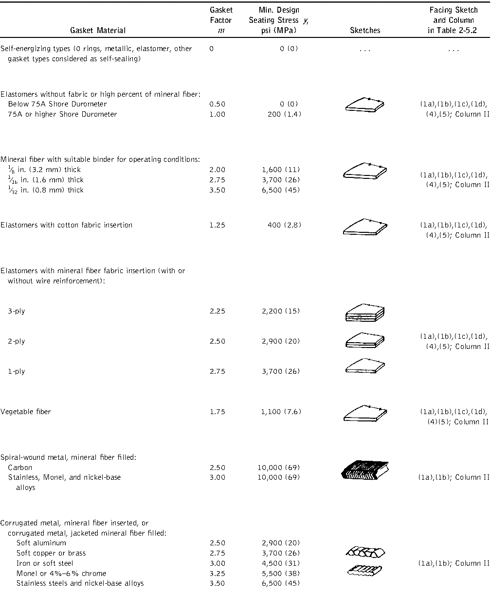
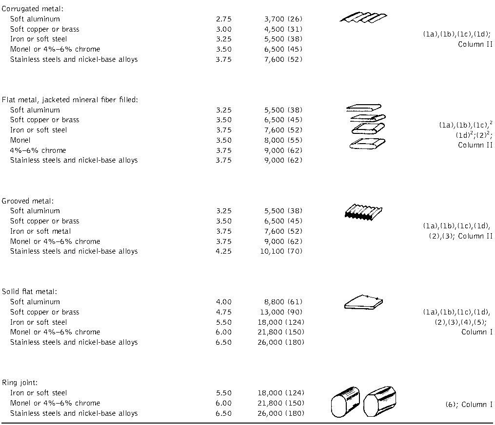
TABLE 2-5.1
GASKET MATERIALS AND CONTACT FACINGS
Gasket Factors m for Operating Conditions and Minimum Design Seating Stress y
GASKET MATERIALS AND CONTACT FACINGS
Gasket Factors m for Operating Conditions and Minimum Design Seating Stress y
NOTES:
(1) This Table gives a list of many commonly used gasket materials and contact facings with suggested design values of m and y that have generally proved satisfactory in actual service when using effective gasket seating width b given in Table 2-5.2. The design values and other details given in this Table are suggested only and are not mandatory.
(2) The surface of a gasket having a lap should not be against the nubbin.
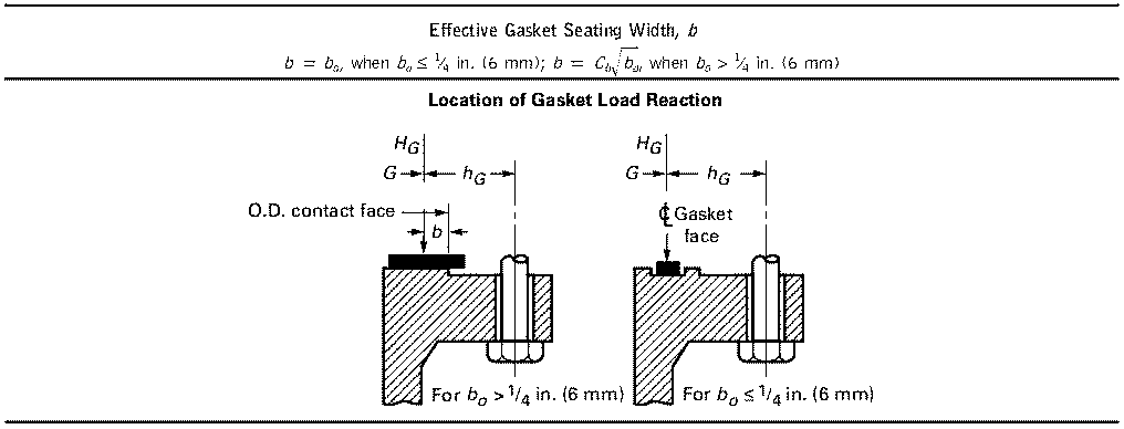
TABLE 2-5.2
EFFECTIVE GASKET WIDTH
EFFECTIVE GASKET WIDTH
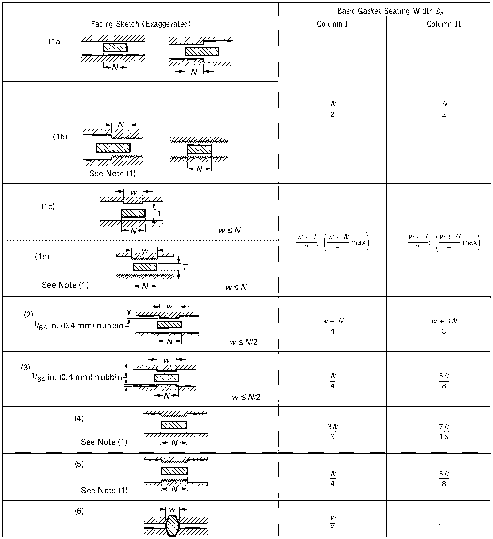
GENERAL NOTE: The gasket factors listed only apply to flanged joints in which the gasket is entirely contained within the inner
edges of the bolt holes.
NOTE:
(1) Where serrations do not exceed 1/64 in. (0.4 mm) depth and 1/32 in. (0.8 mm) width spacing, sketches (1b) and (1d) shall be used.
NOTE:
(1) Where serrations do not exceed 1/64 in. (0.4 mm) depth and 1/32 in. (0.8 mm) width spacing, sketches (1b) and (1d) shall be used.