nomeDoc
nomeDocNum
nomeRedatto
nomeContr
nomeRev
dataEmesso
nomeVessel
nomeItem
nomePlant
um_visua
ASME VIII Div.1 Addenda 11a
2.7
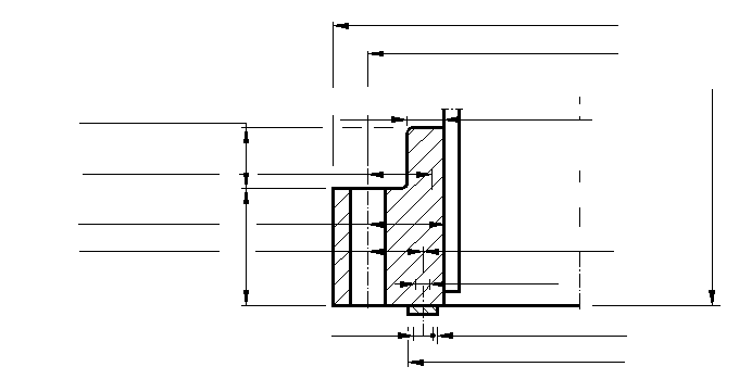
Circular flanges with hub: hub with constant thickness: loose, welded: fig.2-4(3): to internal pressure: gasket laying inside inner edge of bolt holes: with bolt spacing correction
nomeUnit
nomePart
../../Images/vessels/ASME_VIIID1/2_7l3.png
boltnbBspecMaterialFspecMaterialBg1teffdgidgoCAgaskfacingbobbliqheightliqdensGhhhGhDhT
1
designPress
Design pressure: at top:
2
localPress
Design pressure: at location:
3
designTemp
Design temperature:
4
MAWP
Max.allow.working pressure: at top:
MATERIALS
FLANGE
BOLTS
5
ProductB
ProductF
Product form:
6
allowStressB
allowStressF
Allow.stress: at design temperature:
7
allowStressaB
allowStressaF
Allow.stress: at room temperature:
8
 
EF
Elastic modulus: at temperature:
JOINT
9
mm
Gasket factor:
10
yy
Gasket seating stress: minimum:
11
db
Nominal bolt diameter:
12
Bs
Bolt spacing:
13
BSC
Bolt spacing factor:
14
Abolt
Effective bolt cross section area: per bolt:
15
Ab
Effective bolt cross section area: total:
FLANGE RIGIDITY
16
J
Flange rigidity index:
RESULT
17
result
Final result:
www.xcalcs.com
numTotPag
numPag1
(follows on next page)
 
nomeDoc
nomeDocNum
nomeRedatto
nomeContr
nomeRev
dataEmesso
nomeVessel
nomeItem
nomePlant
um_visua
ASME VIII Div.1 Addenda 11a
2.7
Circular flanges with hub: hub with constant thickness: loose, welded: fig.2-4(3): to internal pressure: gasket laying inside inner edge of bolt holes: with bolt spacing correction
nomeUnit
nomePart
(follows from previous page)
FACTORS
18
T
ho
K
19
U
ff
VL
20
Y
Z
FL
21
dd
ee
L
 
OPERATING
GASK.SEATING
22
 
H
Hydrostatic end force: total:
23
 
HHD
Hydrostatic end force: inside:
24
 
HHT
Hydrostatic end force: annular:
25
 
HHp
Gasket compression load:
26
Wm2
Wm1
Minimum bolt load:
27
Am2
Am1
Required bolt section:
28
resultBolt
Result for: Bolt stress:
29
W2
W1
Design bolt load:
30
Mo2
Mo1
Design flange moment:
31
SH2
SH1
Hub stress: longitudinal:
32
SHa2
SHa1
Hub stress: allowable:
33
resultHub2
resultHub1
Result for: Hub stress:
34
SR2
SR1
Radial flange stress:
35
ST2
ST1
Tangential flange stress:
36
SHR2
SHR1
(SH+SR)/2:
37
STR2
STR1
(ST+SR)/2:
38
Sa2
Sa1
Allowable stress for flange:
39
resultFlg2
resultFlg1
Result for: Flange stress:
www.xcalcs.com
numTotPag
numPag2

 <-Forgotten?
Register
Random example
Library (1554)
Beams (527)
Cross sections (44)
Single beam (44)
Tapered (136)
Continuous (20)
Curved (67)
Large defo (18)
Bending+shear (24)
Bending + compression (45)
Bending + tension (45)
Held ends (39)
Elastic foundation (45)
Frames (239)
Arches (285)
Pipes (90)
Plates (299)
Vessels (69)
API Std 650 (2)
ASME I A99 (9)
ASME VIII Div.1 (16)
UG-28 (1)
Appendix 2 (10)
2.7: integral
2.7: Loose+hub
2.7: loose
2.7: lap
2.8: split ring
Bolt spacing corr. (5)
2.7: int.: w.bolt correction
2.7: l.hub: w.bolt correction
2.7: loose: w.bolt correction
2.7: lap: w.bolt correction
2.7: split ring: +bolt corr.
Appendix 24 (2)
Appendix Y (3)
BS 5500:1988 (1)
CODRES (1)
EJMA (1)
EN 13445-3:2002 (16)
Racc.VSR(it) (6)
WRC297 (2)
Volumes (15)
Stability (30)
Other (15)
Search
Options
Show results
Shortened heading
Print sheet
Info/Howto
Contact us
Lingua

If you continue to use this site, we will assume that you accept the use of cookies for statistical and user friendliness purposes. To know more. European Union Directive